Ben Zenker
Science
Work involving scientific concepts and principles.
Science
From Wiggle Animate
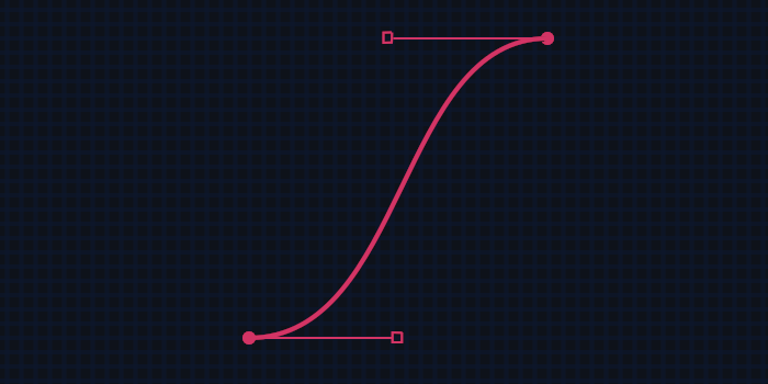
Science, or more specifically mathematics, is at the core of every vector shape and every frame of animation, making it very relevant in the architecture of MicroGraph. What I'd like to highlight is how a Bézier curve, which is often used to represent the vector between two points in 2d space, is also an incredible tool in producing smooth and realistic animations in the 4th dimension, time.
The math that makes it possible to define a curve with 4 points is pretty ingenious, but it's only one of the infinite types of Bézier curves (cubic). You can dive deeper into this topic and play with them visually on this website.
Unfortunately, the general formula defines the curve as a function of how far along the curve you have traveled, which is very different than a traditional x-y series.

Therefore, to use the beautiful shape of a Bézier curve to define the interpolation between two keyframes, we have to solve the curve so that it can be defined in an x & y relationship, or in this case time & interpolated value.
As you might have read in the code section of this project, I've opted for relative values in every way possible. This holds with keyframe interpolation. With both time and value now normalized on a scale of 0 to 1, we can say that P0 and P3 (the first and last points), will always fall at 0,0 and 1,1.
This gives us the power to greatly reduce the complexity in the function, which saves computation time, and eliminates the possibility of imaginary roots existing for a curve. It puts the emphasis, both mathematically and user experience wise, on the handles of the curve -- which are ultimately what define the smoothness and realisticness of an animation.
Science
From CombustionThe beauty of media compression is that if a compression algorithm allows bitrate as an input parameter, you can then, with 100% accuracy, predict the output file size.
The general formula for output size of a video is
Width * Height * BitsPerColor * NumberOfColors *
FramesPerSecond * BitsPerByte * BitsPerSecondRatio *
NumberOfSeconds = OutputFileSize.
What this formula says is: Given a video resolution, the number of colors and how they are represented, the number of video frames to occur in 1 second, here’s how big your file will be.
Let’s take a look at a 1920x1080, 60 FPS video that comes out of a GoPro where the video is 30 seconds long. If the GoPro didn’t add compression to this video, and we just used the basic algorithm above, the file size would be 20GB. That’s insane. So by deciding on a good ratio by which to compress your video, we land on a manageable file of 500 MB.
The point of all of this is, combustion allows you to supply a ratio to your transcode, which is more powerful than supplying “bitrate”, and it’s why applications like Adobe Media Encoder have a “quality” slider. Using this feature and this tool, while at The Molecule, we were able to create a web-playable video of over 10000 media assets and the resulting size of all of them was less than 6GB. And they still looked great when played back in a web browser!
Science
From Camera Shoot-out
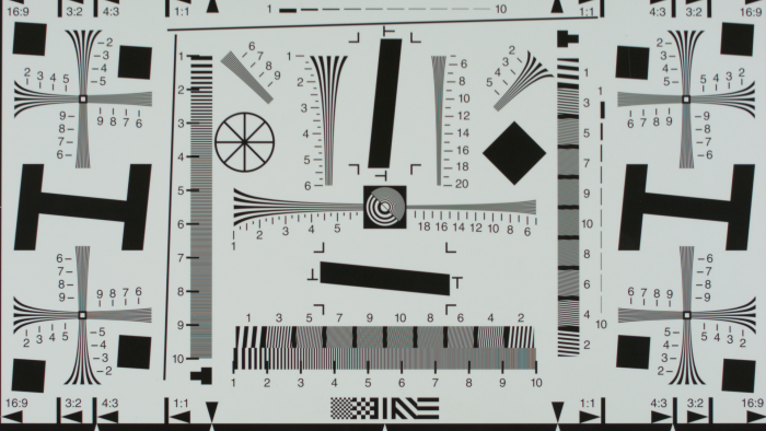
A proper camera shoot-out should include a wide range of scientific measurements and technical comparisons. The learning, planning, preparation, and execution that our team carried out cannot be described simply. We do however have a technical document that explains as much of it as possible.
An excerpt from our conclusion
Based on these findings, the Canon 5D MK III was chosen as the better camera overall for strictly image quality, however, this is only a viable conclusion when your workflow is RAW and contains the necessary knowledge to handle the color grading implications. The Blackmagic Cinema Camera has the best out of the box and easy to use workflow footage that is ready for exhibition straight out of the camera, when shooting in a pre-processed video mode.
Science
From Multi-Camera Array
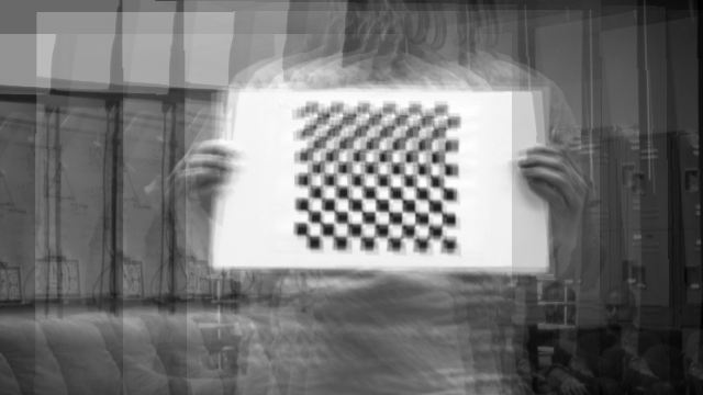
From Above: Using the images of a checkerboard, we can geometrically align the output of each camera to act as if their sensors were part of a singular, larger camera. Content such as this checkerboard was crucial in achieving calibration between each camera. Notice how the images are spread on both the X and Y axis -- as a result of faulty physical calibration when building our camera rig.
Our starting point for scientific research, gifted to us by our professor, was the following video: https://www.youtube.com/watch?v=QNFARy0_c4w
The basic concept of a synthetic aperture is: given geometric control over different regions of your imaging sensor, any focal depth can be chosen by the user, even after the image has been taken.
This is a powerful feature. Imagine taking an important photo or video, only to realize later that what you shot was out of focus. This was the business model of the company Lytro (who has since been purchased by Google), where you will see them reference their captures as light fields, as opposed to images.
Below is an example of a multi-camera array rig from a student at MIT, to give you a visual understanding of what the hardware might look like. You can view our hardware setup in the product section of this project.
